LED Light Matrix
LED Matrix
Preface
This project was made to get a better understaning of how matrixing works, while also getting a better understanding for how to use shift registers. Shift registers were chosen for this project as they allow for the control of multiple outputs, using only 3 data lines for clock, latch, and data signals. This allowed me to use an attiny85 as the dedicated controller for the LED matrix, which makes reprogramming the chip easier, while also minimizing the footprint of the controller. By building this matrix I was made to work with bit shifting and data logic, which was good practice for my university studies in which an understanding of binary data and bit logic is vital to a better understanding of how data is processed within an embedded system. On this project page you will find information on what was used to build this project, how it was constructed/programmed, and any issues or limitations I ran into while working on this project.
Parts and Tools Used
- 1x Attiny85 microcontroller
- 1x 5V DC supply
- 4x SN74HC595 shift registers
- 4x IRFZ44N n-type mosfets
- 4x 1MΩ resistors
- 15x 330Ω resistors
- 20x RGB LED's Common Cathode type
- 4x DIP16 Sockets
- 1x DIP8 Socket
- Insulated copper wire (solid core and stranded)
- 1x Sheet of foam core
- 1x Picture Frame
- 1x Roll of adhesive white vinyl
- Drill press
- Wire strippers
- Soldering iron
- Box cutter
- Straight edge
Construction
The first step of construction was to apply the white vinyl sheet to the glass panel of the picture frame. Unfortunately, in my case, the glass was damaged and the vinyl had to be spread over the entire frame. Following this, separate cells were created for each of the LED's by cutting foam core and adding slots in order to combine them together. These cells were used in order to minimize light bleed between the cells, keeping each cell the colour of its respective LED and not of its neighbours. The final fabrication step was to measure out the center of each cell onto the rear panel of the picture frame and drill a 5mm diameter hole for each cells LED.

Next came the task of installing and connecting all 20 LED's used. This was accomplished by first testing and inserting each RGB LED in the same orientation into their associated hole within the rear panel of the picture frame. These LED's were glued into place using hot glue, and then all Red, Green, and Blue LED pins were wired together into columns, and all ground pins were wired together into rows. Following this, the wires for the columns were matched by colour into 3 groups of 5, along with all grounds into another group of 4, which were then given male headers to allow for easy connection when testing the board. With that, construction of the matrix is complete and we can move onto the circuit and software solution.

A simple mockups of the intended circuit was wired together on a breadboard for testing purposes and an arduino uno was utilized in order to test the full functionality of the circuit and to confirm that an 8MHz clock signal would be sufficient to drive the matrix without significant flickering as that is the maximum speed at which the Attiny can run without an external oscillator. A simple example sketch was written in the arduino IDE to generate randomized colours and cycle on the matrix.
Arduino Files:

The circuit utilized here consists of 4 SN74HC595 Shift registers (3 of which control each colour, with the final one controlling grounds), along with some IRFZ44N mosfets, all controlled by an Attiny85 microcontroller. Following the schematic you can see that busses were utilized to connect the register clock and latch signals together, allowing me to generate an output for the display and send it to the registers all at once. The data signals however pass data from ^H of each register to the data input of the next. This allows data to be cascaded, and enables us to send the 4 Bytes of control data within a single transfer. Also note that all LEDs are given a 330Ω resistor; this is not ideal, and should be balanced for each colour to prevent one colour from outshining the others. Also note that the pull down resistor values do not need to be 1MΩ as shown, but can be any value so long as it is high enough to only pass negligible current. Finally, female headers were used in order to facilitate easier connection with the matrix, however they could be omitted for a direct connection if you wish. Making all connections as shown will create a functional matrix controller; however, if you wish to get more colour control from each of the LED colours (rather than simply on or off), you can replace the ground connection to the output enable line of the three colour registers with a connection to a PWM pin on the utilized microcontoller to get more fine tuned colour control (Note that the Attiny85 does not have enough pins in order to do this for each register).

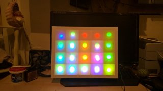
The final result of the board construction as can be seen, showing header connections and jumpers connecting lines together. The board is powered by a 5V wall power supply with a current capacity of 500mA, which due to the fact that no more than 5 LEDs should ever be lit at a time, is more than sufficient to supply the circuit. Due to the number of connections made to and around the Attiny, I opted not to install a programming header, rather, removing the chip and inserting it into a programming shield whenever changes needed to be made. This had the advantage of being easier to accomplish with less work necessary, however it also meant that I had an increased risk of damaging the chips through constantly detaching and reattaching the chip. Other than this, the only other major flaw noticeable on the board is the fact that I used dip18 socets rather than dip16, however this is not an issue, as I simply ignored the unused pins to no detriment.
Conclusion
Throughout completing the design, construction, and programming of this LED matrix I was able to learn valuable information such as, how best to go about wiring LEDs into a matrix; how to better control RGB LEDs, and how to program and use shift registers with Arduino. These skills are incredibly useful when working with tasks such as these, as they allow me to have a better idea of how to go about completing projects and have acquired the skillset neccessary to continue completing such projects.
Odysseus