Custom Hardware Intro Kit
LED Dice Kit
Preface
This project was designed as a teaching tool for a workshop that I ran at Carleton University in hopes of teaching those interested the basics of interfacing software with hardware, and the tools used to do this. The board shown was designed and built by myself, however a slight redesign was made for the workshop to reduce costs. The final production of 30 boards as completed with the help of volunteers from the Carleton Computer Science Society. The board was designed to be very simple in its function and design, requiring very little in the way of components, allowing for an easier explanation of the board function. Through the design of this board I was able to get a better understanding of the process behind board design, production, and was able to utilize arduino sleep functions in order to save power.
Parts and Tools Used
- 1x Attiny45 microcontroller
- 1x SN74HC595 shift registers
- 1x 1KΩ resistors
- 1x 220Ω resistors
- 6x LED's (Red was used)
- 1x DIP16 Sockets
- 1x DIP8 Socket
- 1x 14007 Diode
- 2x CR2037 Battery Clips
- 2x CR2037 Batteries
- 1x Tactile Switch
- 1x Copper Clad Board
- Drill press
- Band Saw
- Wire strippers
- Soldering iron
- Ferric Chloride
- Acetone
Construction
The construction process of this Project began with designing the schematic for the circuit in EagleCAD, where I designed a very rudimentary circuit which came to form the project. An Attiny45 was chosen as the microcontroller due to its low cost, and the fact that it could easily be programmed using the arduino IDE. The Attiny connects directly to an SN74HC595 and a button in order to control the board; the shift register is in turn connected to the 6 LEDs in order to display the output. Note however that only one resistor is used to limit the current to the LEDs; this was done for multiple reasons: firstly, cost is a factor in the design of this board, and the fewer resistors used reduces not only the cost of the resistors, but also the cost of copper clad due to not needing as much space. Another factor in using only one resistor is the fact that the utilized CR2037 batteries are only really rated for a maximum current draw of 20mA, meaning that we cannot drive all LEDs at once without overexerting the batteries. In order to mitigate this, persistance of vision was utilized to rapidly display only one LED at a time quickly enough that you see a fully lit board at all times. The only real drawback of using PoV is that the intensity of each LED is reduced, however this is not significant for this project.
It can also be noted that a diode connects between the grounds of the IC's and the batteries; this was done to act as a low cost voltage regulator. The Attiny is not designed to run at voltages below 2.5V which would mean that 1 CR2032 would only be able to power it for about 1/3 of its total life which would be too wasteful. The only options at this point would be to either purchase higher cost low voltage chips or to use a seconf battery to increase the minimum voltage of the circuit to about 3.5V. The second option was chosen as it was a lower cost option, however this meant that the maximum voltage was now 6V which exceeded the Attiny's 5.5V maximum. This was solved by using the voltage drop of a diode to reduce the voltage to the chip by 0.7V meaning that the maximum is now 5.3V with a minimum of 2.8V. These values are well within the range of operation of the chips and ensured that the board would be able to maximize the useful lifespan of the CR2032's.

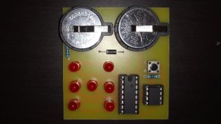
Following circuit design came the stage of board layout, wherein I maximized space savings while still leaving enough space for the board to have a relatively attractive layout. The LEDs were laid out in the shape of a die in order to more easily visulaize the rolled values from the dice, with both ICs laid out next to eachother and the LEDs. Note however that there is no programming header present on the board, this was added to the final boards, but this example board was able to make due with removing the Attiny for programming. It can also be observed that the trace widths used are significantly more than necessary for the current being used, however this results in an easier to etch board, and so was chosen more for ease of production than for appropriate current flow.
Following board design came the process of etching the board; for this project I utilized the toner transfer method, however it quickly became apparent during production of the distribution boards that the toner transfer method scales incredibly poorly. So much so in fact, that in future if I find myself needing to make multiples copies of a board I will likely instead make use of a PCB milling service. Despite this, the initial test board turned out quite well using the toner transfer method, and it is sufficient for making small numbers of boards. An issue I also had to deal with when producing the board was that I had accidentally mirrored the image file, resulting in an unuseable board. Regardless of these issues, I was able to etch the board relatively quickly, and drilled all of the marked holes using a 0.8mm drill bit for the component leads, and a 1mm bit for the battery and diode terminals.
With a fully prepared board in hand I proceeded on to the process of soldering on all of the components for the circuit using lead free solder. The circuit came together rather nicely following soldering and was ready for programming. The programming of this board was of significant importance as the code needed to be effective and easily understood in order to be understood by those at the workshop. The first task I had set out for myself was to generate a simple test script, in which, when a button is pressed it will light a single LED in the list in order to confirm that data is being shifted and read correctly. Following the confirmation that the circuit is functional I moved onto writing the code that would wakeup the Attiny from sleep and roll the die when the number is pressed. This was done through a number of processes. Firstly the Attiny would go into sleep mode, with the button set as an interrupt to wake it on changing states; sleep was achieved using the arduino sleep library to give access to nicer commands, and utilizing some register manipulation to put the chip into low power mode. Upon waking up the Attiny would send multiple die states to the register to simulate a roll, finally landing on a value that would be displayed for about 2 seconds. The numbers were chosen using the XOR value between the timing registers on the Attiny, this gives rather poor rando performance, but is far better than the arduino random function which eventually begins returning the same results consecutively. I may write a better random function in future, however for now this function served the purpouse sufficiently well. The number was then sent to a function which would write out the selected value to the die face one LED at a time for a given amount of time. Following the completion of displaying a number then Attiny would reset itself to its initial state, which is a rather crude hack to fix a memory leak caused by the millis command. In future I plan to fix this function removing the need for the reset at the end of the loop, however for now it is functional.
Other issues that I ran into throughout this process include the fact that the arduino power function returns a floating point number, which is always rounded down when converted to an int. This caused problems when attempting to send data to the LED display as many values would be off by 1 when attempting to send powers of 2 to the display. Upon realizing this mistake however it was mitigated through the use of bitshifting in order to shift the value 1 over a number of bits equal to the power, resulting in an accurate integer result. It may also be noticed that the display did not need the control og a shift register in order to produce its output, as pairs of LEDs could be combined in such a way that only 4 Attiny pins are needed, however the regster was included in order to give more control over outputs, as well as to enable those attending the workshops to learn more about bit shifting.
Arduino Scripts:
Conclusion
This project was fun, and let me play with adding lots of features to a project that intially only had 1. It was alot of fun, and taught me some liitations of working with Arduino as well. One major issue I had while building this project was a shift register with a damaged pin was leaking through one of its pins, and was frying one LED consistently. Another issue I ran into was a discovery I made in working with the Piezo Electric Speaker, wherein it appears that the is some small amount of crosstalk between PWM pins on the arduino, meaning that it is picking up small amounts of current and making sounds when the PWM register is altered. Despite these limitations, the project was still fun to work on, and I believe the end result turned out rathe well. I hope to continue adding features to this project in the future, and will likely update this post following.
LED Matrix